|
Volume and design of a cell are determined by the type and size of the working electrode and the goal of a certain measurement you want to do: Large electrodes require large volumes of the solution (usually, not necessarily). Fast measurements are best using small electrodes and small cell volumes. However, these are coarse rules and not laws. |
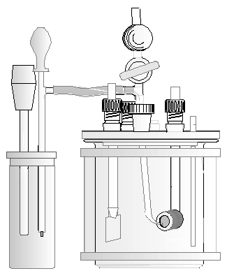
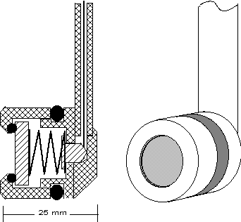
| Fig. 1: Universal Cell |
But it shows, that a really universal cell which delivers best result under all conditions cannot be realised. However, you will find so - called "universal cells" on the market. They got the designation because they offer convenient work for many different applications, as long as the working electrode area is in the order of some cm². They are made of glass, they have enough openings to insert different types of electrodes, thermometers, gas injectors or other auxiliary equipment.
Such a universal cell consists of a glass beaker with plane sleeve, the volume may be 0.25 l to 1 l. The lid should have at least 6 sleeve sockets to take up the electrodes and auxiliary equipment. A large sleeve for a reflow - condenser may be desired, too. Usually, the reference electrode is installed in a separate container, and connected to the main electrolyte by an electrolyte bridge.If products are formed at the counter electrode which must not enter the main electrolyte, also the counter electrode must be installed in a separate cell compartment which is connected to the cell by a frit.
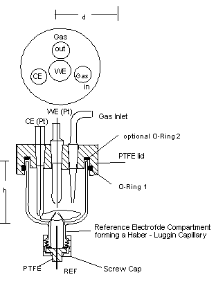
Fig. 2: 20 - ml - Cell, d about. 40 mm, h about. 35 mm.
Very fast measurements require small volumes of the cell. Instead of a calomel electrode, low-ohmic reference electrodes are required, long electrolyte bridges to the reference electrode should be avoided.Cells, which are used for electrochemical analyses should be small to keep the required volume of the reagent to be tested as small as possible.
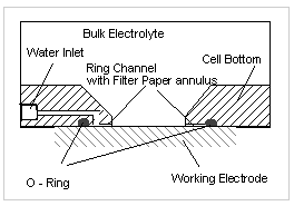
Fig. 3 Construction of the cell bottom of the Avesta - Cell
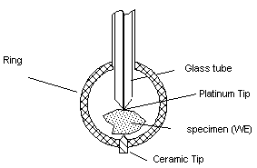
To exclude this effect, different special designs have been developed: One of it is the so - called Avesta cell, designed by Rolf Qvarfort. In this cell, an artificially produced crevice is passed at very low rate through this crevice, which prevents the material from crevice corrosion.If working electrodes are completely immersed in the electrolyte, it may be contacted using simply a platinum wire wrapped around the electrode. This method is applicable as long as the measurement is restricted to anodic currents, due to the difference in hydrogen overvoltage between the electrode metal and platinum. If the platinum tip is very small compared to the working electrode area (less than 1/1000), also the cathodic currents are governed by the reaction at the working electrode.
|
|
Left: Problems may arise when gas bubbles are formed at the electrode. | Right: No problems by gas bubbles on vertically faces. |
 |
 |
 |
| Fig. 5: Electrode fixture for mounting disks | Fig. 6: Electrode fixture for irregularly shaped electrodes |
The electrolyte is transported tangentially along the surface of the RDE. Its flow is laminar up to very high speed. Therefore, diffusion limited currents can be measured quite exactly.
Rotating Cylinders are used when turbulent flow at the electrode surface is desired.Ring - disc - electrodes allow to analyse intermediate products produced at the disc electrode. Their life-time can be determined by variation of the electrode speed.
If you are interested in such electrodes, there is quite a lot of literature describing the techniques.To keep the electrolyte of the reference cell clean, it is usually separated from the cell using a separated reference cell beaker, which is connected by a liquid junction to the cell which contains the working electrode. Frits or gel - electrolytes are used to prevent inter - diffusion of the different electrolytes. However, long bridges have high electric resistance and may affect fast measurements. In such cases, a platinum wire along the electrolyte bridge helps to decrease the AC - impedance of the bridge (it must not be connected to one of the electrodes!) Instead a frit, a platinum wire, molten into a common laboratory glass tube (DURAN or PYREX) acts like a low - ohmic frit by forming a ring - crevice between glass and platinum. The ring crevice is necessary to form the liquid junction, therefore no glassware must be used which usually is used for melting platinum wires into glass tubes! They do not form such crevices, and you will not be able to measure correct potentials!
One of the most common problems is the formation of gas bubbles within the electrolyte bridge. Gas bubbles increase the electrical resistance, and may lead to complete interruption of the liquid junction. For most purposes, a cotton thread inside the bridge will form an "emergency junction" which will care for stable operation.Usually, the electrolyte bridge has got a capillary tip pointing to the working electrode. This capillary is called "Haber - Luggin - Capillary" (HLC). Its position with respect to the working electrode determines the correctness of the true electrode potential during potentiostatic measurements.
If a current is passed between counter electrode and working electrode, a voltage drop across both electrodes arises.
The ideal location for potential measurement now should be inside the double layer at the working electrode. At any other place, part of the voltage drop between CE and WE is added to the WE potential. This error is called "ohmic drop" or "IR - drop", because the resistance of the electrolyte causes the error.
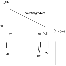
Fig. 8 Ohmic drop between WE and the location of potential measurement
The ohmic drop is I * R, with I = current between WE and CE, and R = electrolyte resistance. From the graph, it is clear that I * R is zero as soon as the reference electrode is infinitely close to the working electrode. This is not practicable in a real cell. However, a tipped capillary at the electrolyte bridge allows to position the virtual point of potential measurement quite close to the working electrode.Usually, a capillary tip of 1 mm diameter at a distance of 0.5 to 1 mm is a good compromise. However, setting the capillary closer to the working electrode will form shielding effects and introduce other sources of potential errors.
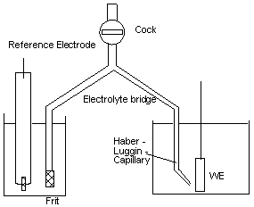
Fig. 9: Typical setup of the liquid junction with HLC.
As a rule, the electrolyte in the cell is different from that within the reference electrode container. Therefore, a frit is used to impede inter - diffusion between both electrolytes. The frit can be positioned either close to the HLC, or at the other end of the electrolyte bridge.Both positions of the frit have some drawbacks. Is the frit close to the working electrode, the risk of contamination of the main electrolyte in the cell is high. In addition, the diameter of the frit will be increased, which requires larger distance from the working electrode. This increases the IR - drop error.
If the frit is positioned close to the reference electrode, the risk of electrolyte contamination is reduced in the main cell, but instead the contamination of the reference electrode container will increase. If the main electrolyte has low conductivity, the electrolyte bridge forms a series resistor which increases noise pick - up. The bridge then should be kept as short as possible, and its diameter should be wide enough.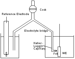
Fig. 10: HLC with a frit close to the working electrode
For short - term - measurements, where electrolyte inter - diffusion is not the major problem, reference electrodes built into the HLC give best results, as their internal resistance is rather low.
 The only condition of a counter electrode is, that is must not dissolve
in the electrolyte. Only noble metals and carbon fulfil this
condition perfectly. In some cases, corrosion - resistant alloys
with large surfaces will meet the requirements, especially if only
anodic currents occur at the working electrode. If a large active
surface of the CE is required, platinum coated with platinum black
will give best results. Also this coating is a process which can be
done using your potentiostat, by electrolytic deposition of platinum
from a platinum chloride solution. Carbon electrodes form CO2
when polarised to high anodic potentials. This polarisation is reduced
if the CE area is increased, thus decreasing the current density at the CE.
The only condition of a counter electrode is, that is must not dissolve
in the electrolyte. Only noble metals and carbon fulfil this
condition perfectly. In some cases, corrosion - resistant alloys
with large surfaces will meet the requirements, especially if only
anodic currents occur at the working electrode. If a large active
surface of the CE is required, platinum coated with platinum black
will give best results. Also this coating is a process which can be
done using your potentiostat, by electrolytic deposition of platinum
from a platinum chloride solution. Carbon electrodes form CO2
when polarised to high anodic potentials. This polarisation is reduced
if the CE area is increased, thus decreasing the current density at the CE.
A simple counter electrode is formed by a platinum wire
The geometry of the WE - CE setup is to be regarded when high currents are required. In that case, symmetrical arrangements are useful, either co - planar or cylindrical ones.
We supply cells and electrodes.
Back Home