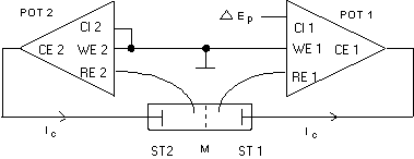

POT 1 controls the reference electrode RE 1 of the cell compartment 1 to virtual ground, as the control input CI 1 of POT 1 is grounded. The current that maintains this potential is delivered by the counter electrode CE 1. POT 2 controls the potential of the reference electrode RE 2 in the second compartment to that potential which is fed into the control input CI 2 of POT 2, resulting in a controlled potential difference between the two faces of the membrane.
The current that maintains the potential difference flows between the two controlling electrodes ST 1 and ST 2, they must be connected to the counter electrode terminals CE 1 and CE 2.To avoid ring earths, the ground bridge of POT 2 must be removed. Both terminals WE 1 and WE 2 are then connected. For the measurement of small currents it is helpful to screen the cell as well as the cables. Note: When using our "current sink" potentiostats, LB 95 L, LB 94 AR, or POS 88 (or their predecessors LB 75 L and POS 73), the connection between WE 1 and WE 2 must be connected to ground on either side. In that case, also this connection between WE 1 and WE 2 must be screened. Reason: The working electrode of these potentiostats is not really grounded, but kept to virtual ground.
To measure current - potential curves in this mode, the control input CI 2 of POT 2 must be used. As long as no overload lamp starts to glow, the potential difference is equal to the voltage fed into CI 2.
| TOC | Back | Next | ||
| Back Home | ||||