If the working electrode itself is subject of an investigation, its geometry usually is not a subject of electrode design. In other words: The size and shape of the working electrode defines the cell design. Usually, only certain faces of a material are subject of an investigation. The other faces have to be excluded from the electrolyte. To do this, different methods are used.
A good coating will do it in most cases, but it has to meet some conditions. A good coating must be chemically stable in the given electrolyte, it shall not form crevices (see above) and it shall not release any chemicals into the electrolyte which may influence the measurement. Only a few commercially available products meet these requirements, usually, epoxy - based resins or coatings.
Cylindrical electrodes can be mounted in PTFE- blocks. To keep it crevice - free (as good as possible), the diameter of the electrode should be slightly larger than the bore of the PTFE block. Heat the PTFE to 100°C or more (Tins) and insert the cold specimen. The coefficient of thermal expansion of PTFE is much higher than that of metals, so the cold metal will fit into the bore. When cooling, PTFE shrinks and, due to its easy plastic deformation, it will fit very good. However, the bath temperature of electrolytes is also limited - as a rule, the bath temperature shall not exceed half of the difference between room temperature and the temperature (Tins).
If working electrodes are completely immersed in the electrolyte, it may be contacted using simply a platinum wire wrapped around the electrode. This method is applicable as long as the measurement is restricted to anodic currents, due to the difference in hydrogen overvoltage between the electrode metal and platinum. If the platinum tip is very small compared to the working electrode area (less than 1/1000), also the cathodic currents are governed by the reaction at the working electrode.
|
|
Left: Problems |
|
Right:
No problems by gas bubbles on vertically faces. |
|
|
|
|
|
|
Fig. 5: Electrode fixture for mounting disks |
|
Fig. 6: Electrode fixture for irregularly shaped electrodes |
|
Rotating electrodes are used to investigate transport mechanisms in the electrolyte, or simply to get ideally reproducible conditions in a cell. Rotating electrodes require good mechanic quality of the rotating parts, and good rotating contacts. Usually, mercury contacts are required if low currents shall be transferred without noise generated by the rotating contact.
The electrolyte is transported tangentially along the surface of the RDE. Its flow is laminar up to very high speed. Therefore, diffusion limited currents can be measured quite exactly.
Rotating Cylinders are used when turbulent flow at the electrode surface is desired.
Ring - disc - electrodes allow to analyse intermediate products produced at the disc electrode. Their life-time can be determined by variation of the electrode speed.
If you are interested in such electrodes, there is quite a lot of literature describing the techniques.
A reference electrode is a complete half - cell, maintaining a stable potential. Commonly, calomel electrodes or silver/silver chloride electrodes are used. In chloride - containing solutions, a simple silver wire will form a good reference electrode. Depending on the electrolyte, other reference electrodes may be preferred: Hg/HgO electrodes in strongly basic solutions, Hg/HgSO4 - electrodes in sulphuric acids. All these electrodes are stable as long as "electrode poisons" are not allowed to enter the reference electrolyte. Special reference electrode systems are required in molten salts.
To keep the electrolyte of the reference cell clean, it is usually separated from the cell using a separated reference cell beaker, which is connected by a liquid junction to the cell which contains the working electrode. Frits or gel - electrolytes are used to prevent inter - diffusion of the different electrolytes. However, long bridges have high electric resistance and may affect fast measurements. In such cases, a platinum wire along the electrolyte bridge helps to decrease the AC - impedance of the bridge (it must not be connected to one of the electrodes!) Instead a frit, a platinum wire, molten into a common laboratory glass tube (DURAN or PYREX) acts like a low - ohmic frit by forming a ring - crevice between glass and platinum. The ring crevice is necessary to form the liquid junction, therefore no glassware must be used which usually is used for melting platinum wires into glass tubes! They do not form such crevices, and you will not be able to measure correct potentials!
One of the most common problems is the formation of gas bubbles within the electrolyte bridge. Gas bubbles increase the electrical resistance, and may lead to complete interruption of the liquid junction. For most purposes, a cotton thread inside the bridge will form an "emergency junction" which will care for stable operation.
Usually, the electrolyte bridge has got a capillary tip pointing to the working electrode. This capillary is called "Haber - Luggin - Capillary" (HLC). Its position with respect to the working electrode determines the correctness of the true electrode potential during potentiostatic measurements.
If a current is passed between counter electrode and working electrode, a voltage drop across both electrodes arises.
|
|
Fig. 7 Ohmic drop between WE and CE
The ideal location for potential measurement now should be inside the double layer at the working electrode. At any other place, part of the voltage drop between CE and WE is added to the WE potential. This error is called "ohmic drop" or "IR - drop", because the resistance of the electrolyte causes the error.
|
|
|
Fig. 8 Ohmic drop between WE and the location of potential measurement
The ohmic drop is I * R, with I = current between WE and CE, and R = electrolyte resistance. From the graph, it is clear that I * R is zero as soon as the reference electrode is infinitely close to the working electrode. This is not practicable in a real cell. However, a tipped capillary at the electrolyte bridge allows to position the virtual point of potential measurement quite close to the working electrode.Usually, a capillary tip of 1 mm diameter at a distance of 0.5 to 1 mm is a good compromise. However, setting the capillary closer to the working electrode will form shielding effects and introduce other sources of potential errors.
|
|
|
Fig. 9: Typical setup of the liquid junction with HLC.
As a rule, the electrolyte in the cell is different from that within the reference electrode container. Therefore, a frit is used to impede inter - diffusion between both electrolytes. The frit can be positioned either close to the HLC, or at the other end of the electrolyte bridge. |
|
|
Fig. 10: HLC with a frit close to the working electrode
Both positions of the frit have some drawbacks. Is the frit close to the working electrode, the risk of contamination of the main electrolyte in the cell is high. In addition, the diameter of the frit will be increased, which requires larger distance from the working electrode. This increases the IR - drop error. If the frit is positioned close to the reference electrode, the risk of electrolyte contamination is reduced in the main cell, but instead the contamination of the reference electrode container will increase. If the main electrolyte has low conductivity, the electrolyte bridge forms a series resistor which increases noise pick - up. The bridge then should be kept as short as possible, and its diameter should be wide enough. |
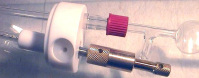
![]() Haber - Luggin - Tip:
Haber - Luggin - Tip:
If you have a Bunsen burner, you can shape the HLC easily. Take care not to make it too narrow, for very narrow capillaries have high electric resistance which make it prone for noise - pickup. If the electrolyte resistance is very high (e.g. when using distilled water as electrolyte) it will be necessary to use quite different constructions, e.g. to built the reference electrode into the HLC. In those cases, a platinum wire may be a kind of reference electrode which - as long as the oxygen concentration of the solution is constant - allows reliable potential measurements (which, of course - have to be calibrated using a standard reference electrode).
For short - term - measurements, where electrolyte inter - diffusion is not the major problem, reference electrodes built into the HLC give best results, as their internal resistance is rather low.
The only condition of a counter electrode is, that is must not dissolve in the electrolyte. Only noble metals and carbon fulfil this condition perfectly. In some cases, corrosion - resistant alloys with large surfaces will meet the requirements, especially if only anodic currents occur at the working electrode. If a large active surface of the CE is required, platinum coated with platinum black will give best results. Also this coating is a process which can be done using your potentiostat, by electrolytic deposition of platinum from a platinum chloride solution. Carbon electrodes form CO2 when polarised to high anodic potentials. This polarisation is reduced if the CE area is increased, thus decreasing the current density at the CE.
For common use, a platinised titanium electrode is best choice. It has the advantage of superior mechanical stability, while the electrochemical properties are in most environments identical to those of platinum metal.
A simple counter electrode is formed by a platinum wire
The geometry of the WE - CE setup is to be regarded when high currents are required. In that case, symmetrical arrangements are useful, either co - planar or cylindrical ones.
Bank Elektronik -
Intelligent Controls GmbH
Hubertusstr. 38
D-35415 Pohlheim
Tel. +49 - 6403 - 60 98 60
Fax +49 - 6403 - 60 98 622
e-Mail: info [at] bank-ic.de